Projects

Project 01 · Formula SAE

NovaRacing

Villanova's Formula SAE team designs and builds an open-wheel formula race car from scratch every year. I work as a Chassis System / Aerodynamics Subsystem Engineer, moving from composite manufacturing my first year to CAD- and CFD-driven aero design now.

Role Chassis System / Aerodynamics Subsystem Engineer Team NovaRacing Formula SAE, Villanova University Timeline Dec. 2025 – Present
Fall Recruitment

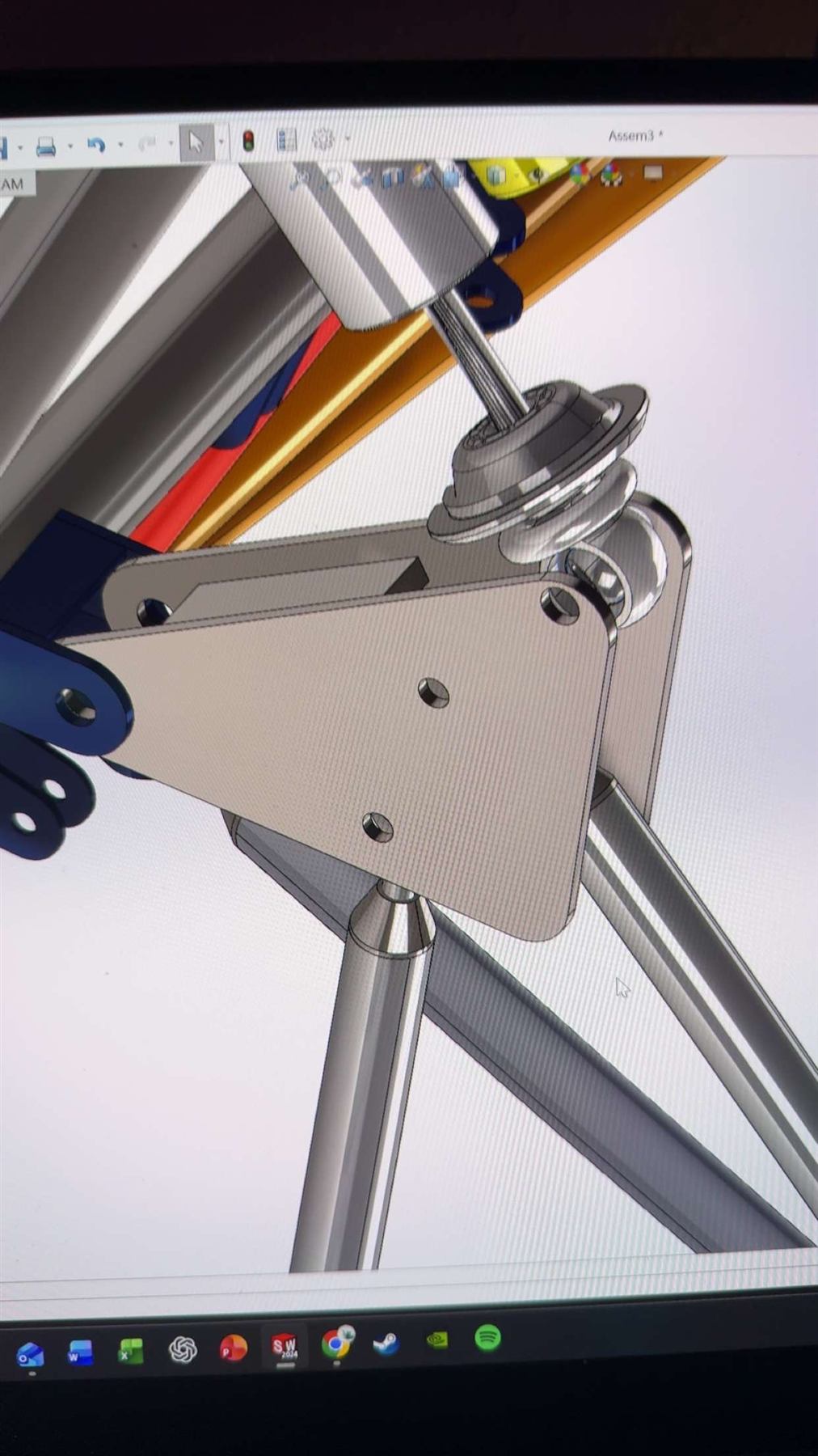
NovaRacing's fall recruitment process ran from September through December and consisted of three engineering projects designed to introduce applicants to the team's design process. The final project focused on learning the fundamentals of SolidWorks by designing a suspension rocker from a given set of geometric and loading requirements.

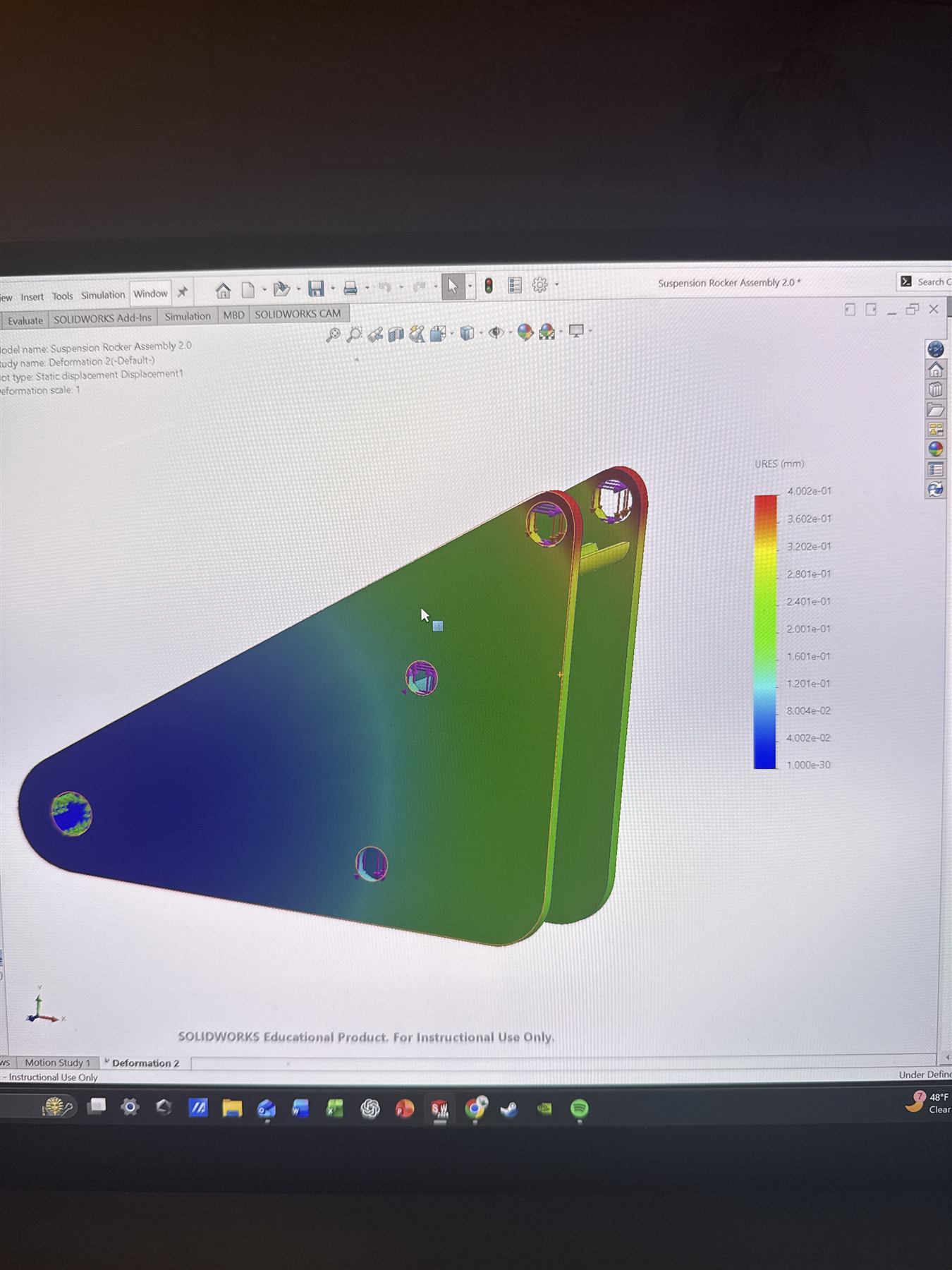
After creating the CAD model, I used finite element analysis (FEA) to compare candidate materials, evaluate stress and deformation, and determine the most appropriate material for the component. The project introduced me to parametric modeling, simulation-based material selection, and the connection between component geometry, loading, and manufacturability.

FEA stress and deformation study on a suspension rocker
FEA stress & deformation study on the suspension rocker
Suspension rocker assembly with coilover, modeled in SolidWorks
Modeled in SolidWorks
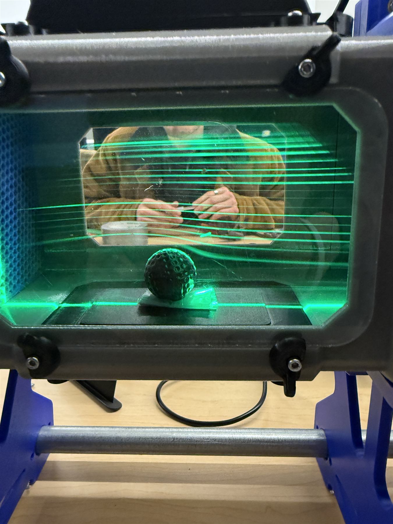
Laser sheet flow visualization over a dimpled sphere in the wind tunnel lab
Flow visualization in the wind tunnel lab: laser sheet over a dimpled sphere
Getting Acquainted

After the rigorous recruitment process was complete in the winter, only about thirty of the two-hundred initial interest-meeting attendees made the team. At first, I was reluctant to go to the shop because the team and all the machines were admittedly intimidating. My mistake was thinking I was set, and that my background knowledge would carry me through this club. I could not have been more wrong.

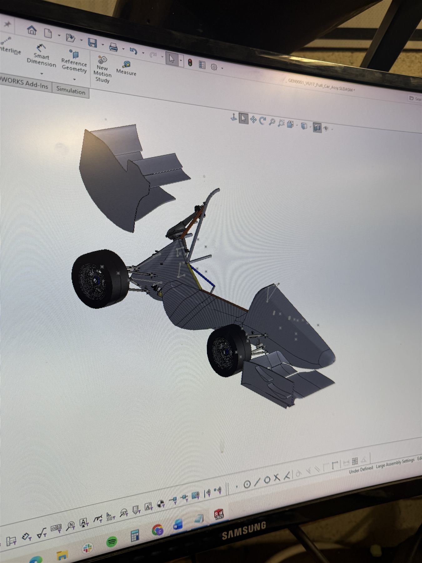
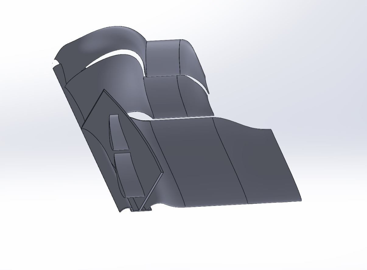
This is one of the first images from the very beginning of my journey as an engineering student: exposing myself to the wind tunnel lab, modeling my first parts in SolidWorks, and playing around with basic assemblies. I knew very quickly that there were many levels to engineering and much more to learn.

That first month passed, and I was already feeling so much more confident in my abilities as an engineer. I had brushed up on just enough aerodynamic theory to keep up with the senior capstone team, who I would soon join in my greatest contribution to NovaRacing Formula SAE.

Aero Sprint

As the spring semester began, the push to finish VU17 quickly became an all-out aero sprint. The car had fallen months behind schedule, leaving the team with very little of the time originally set aside for manufacturing and testing before competition at Michigan International Speedway 2026. With the deadline approaching, everyone in the garage had a role to play. As a freshman, much of my early work involved sanding, filling, and gluing mold structures. In just three months, our team manufactured and finished a complete aerodynamic package for competition, including the front and rear wings, undertray, nosecone, sidepods, and body panels.

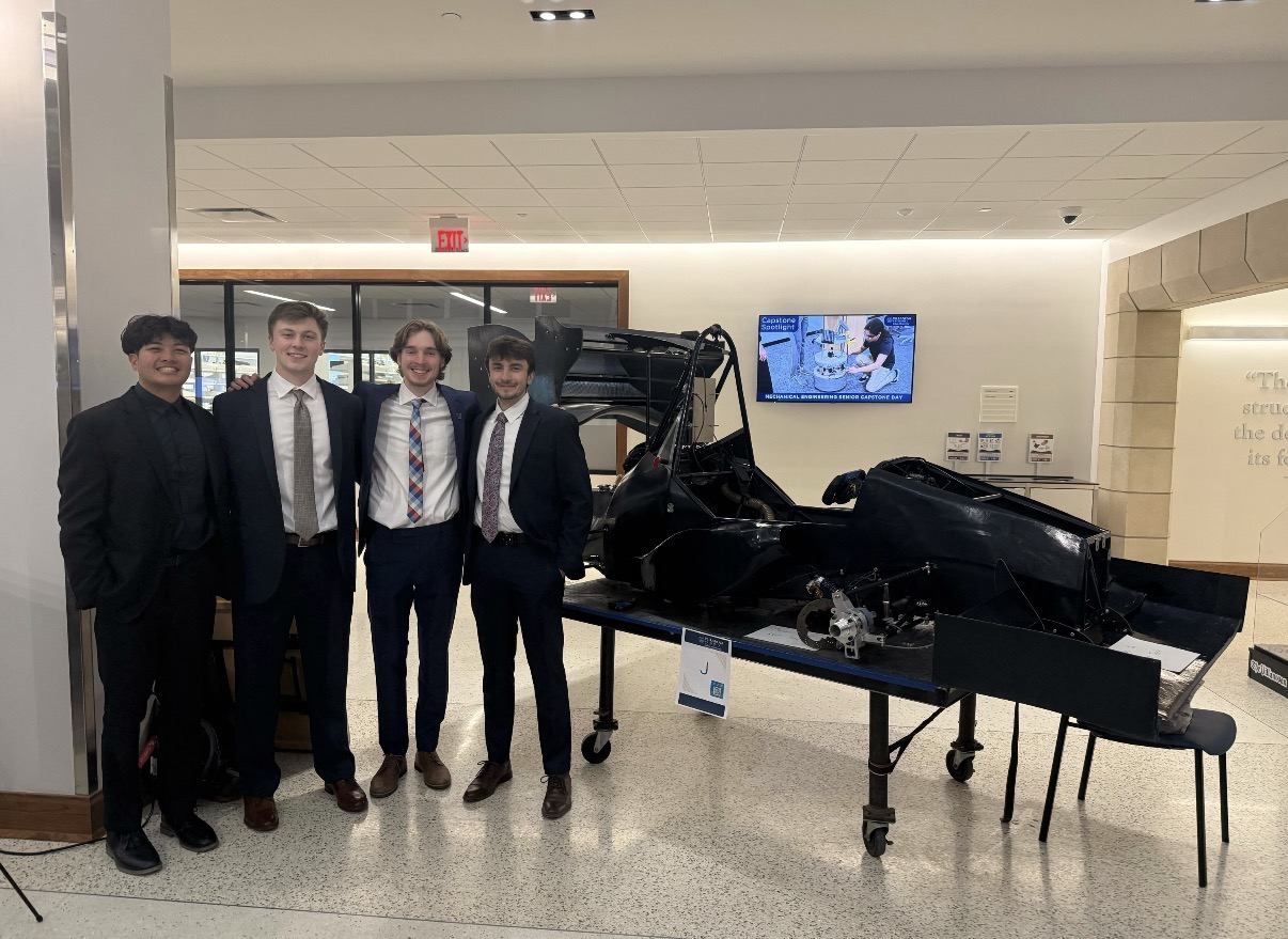
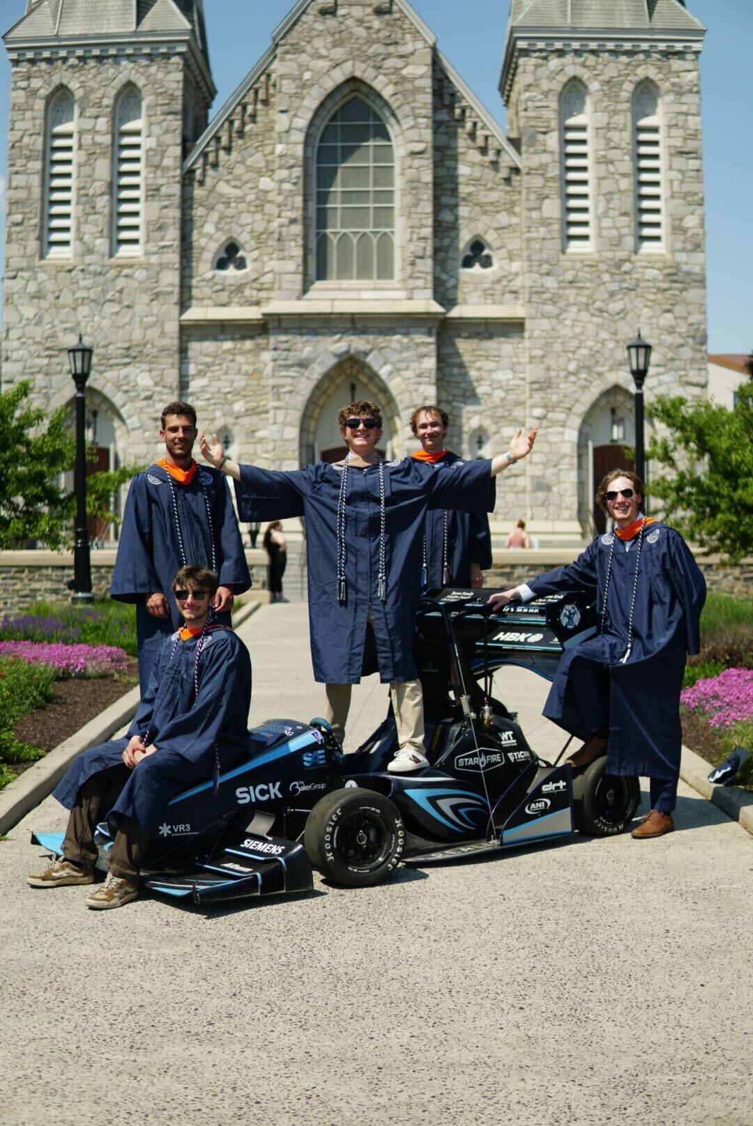
The VU17 senior capstone team
Senior Capstone Team (left to right): Jase Co, Chassis & Frame; James Breckner, Powertrain; Conner Brett, Aerodynamics; Chris Fleschner, Chief Engineer & VU17 Aerodynamic Package Designer
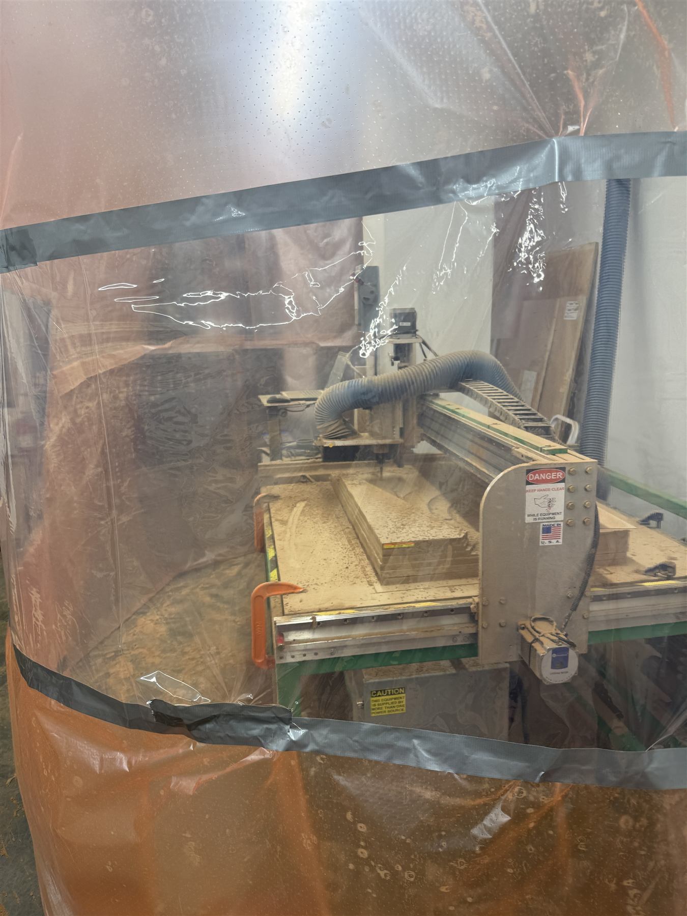
CNC router cutting a mold from MDF
CNC Router cutting MDF sheet stock for undertray mold
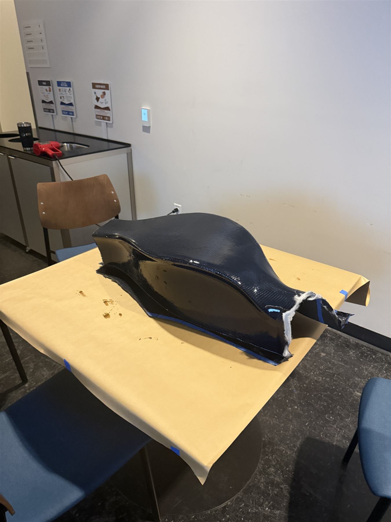
First completed carbon-fiber sidepod, untrimmed
The first completed carbon structure (untrimmed): the aerodynamic sidepod. Sealing its seam with the body panels became a cooling issue that needed some sketchy duct tape at competition.
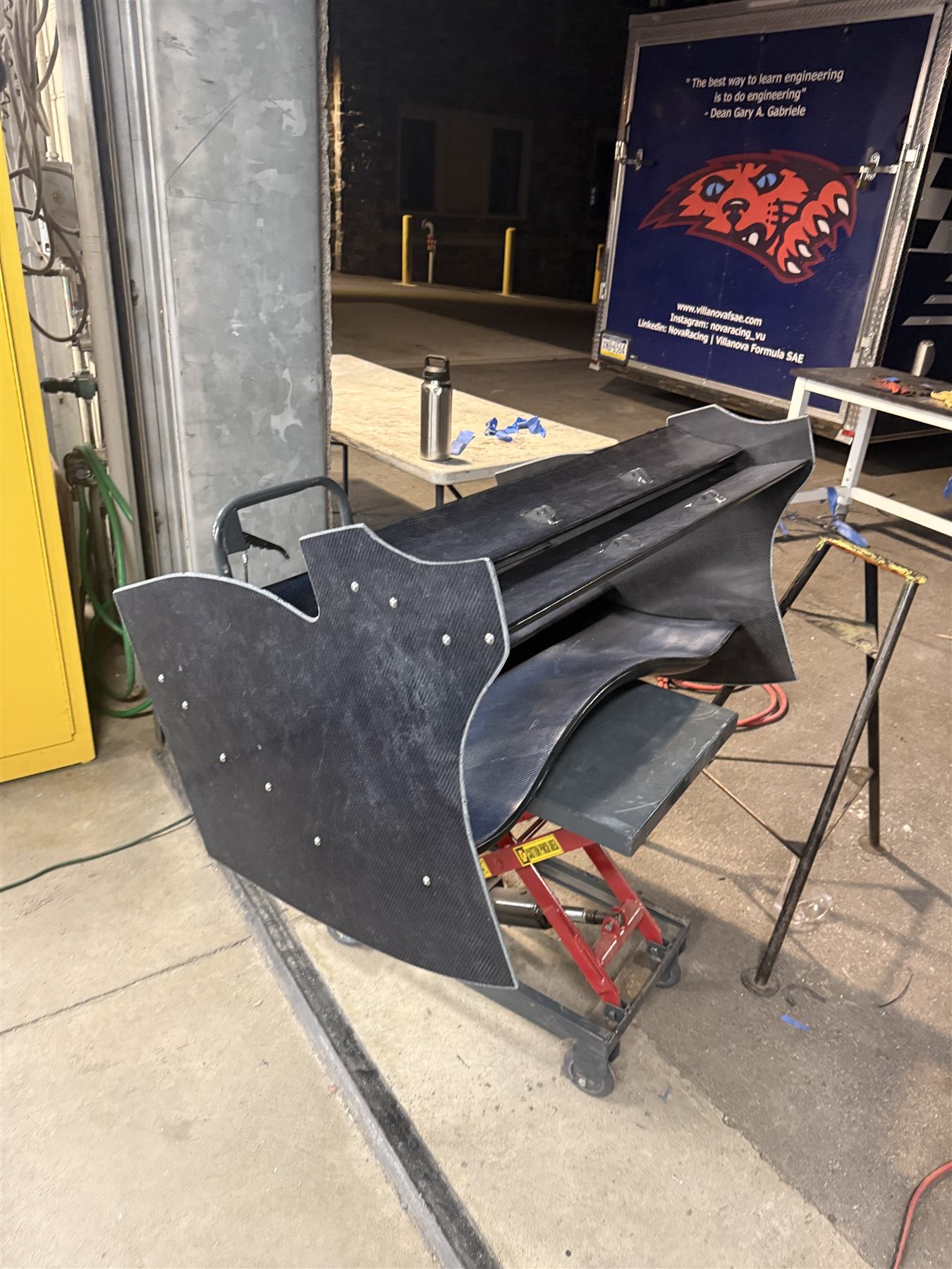
Near-finished rear wing and endplate assembly
Near-finished rear wing, before mounting to the frame. A laser-cut endplate stencil set mounting holes for an adjustable angle of attack, tuned to -1° for the S1223 airfoils to achieve the lowest drag.
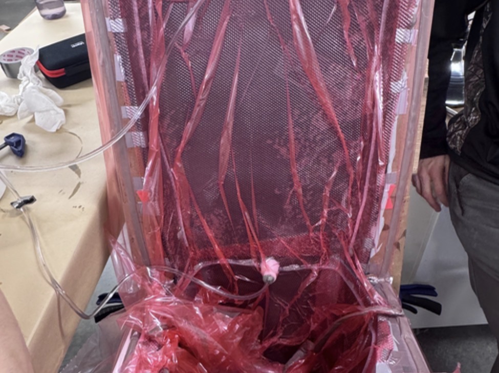
Nosecone resin infusion layup, vacuum-bagged for cure
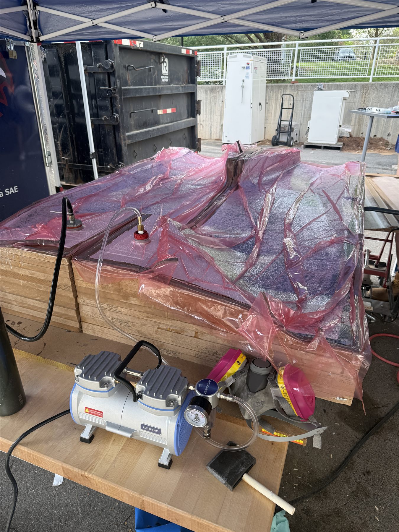
Nosecone resin infusion layup with a 10:3 resin-to-hardener formula to achieve optimal resin volume and distribution across the nosecone surface
Composite Manufacturing & Aerodynamic Finishing

Producing the VU17 aerodynamic package involved much more than laying carbon fiber into a mold. Every component had to move through a complete manufacturing process while meeting tight deadlines, fitting within the Formula SAE dimensional envelope, and remaining stiff, lightweight, accessible, and properly aligned on the car.

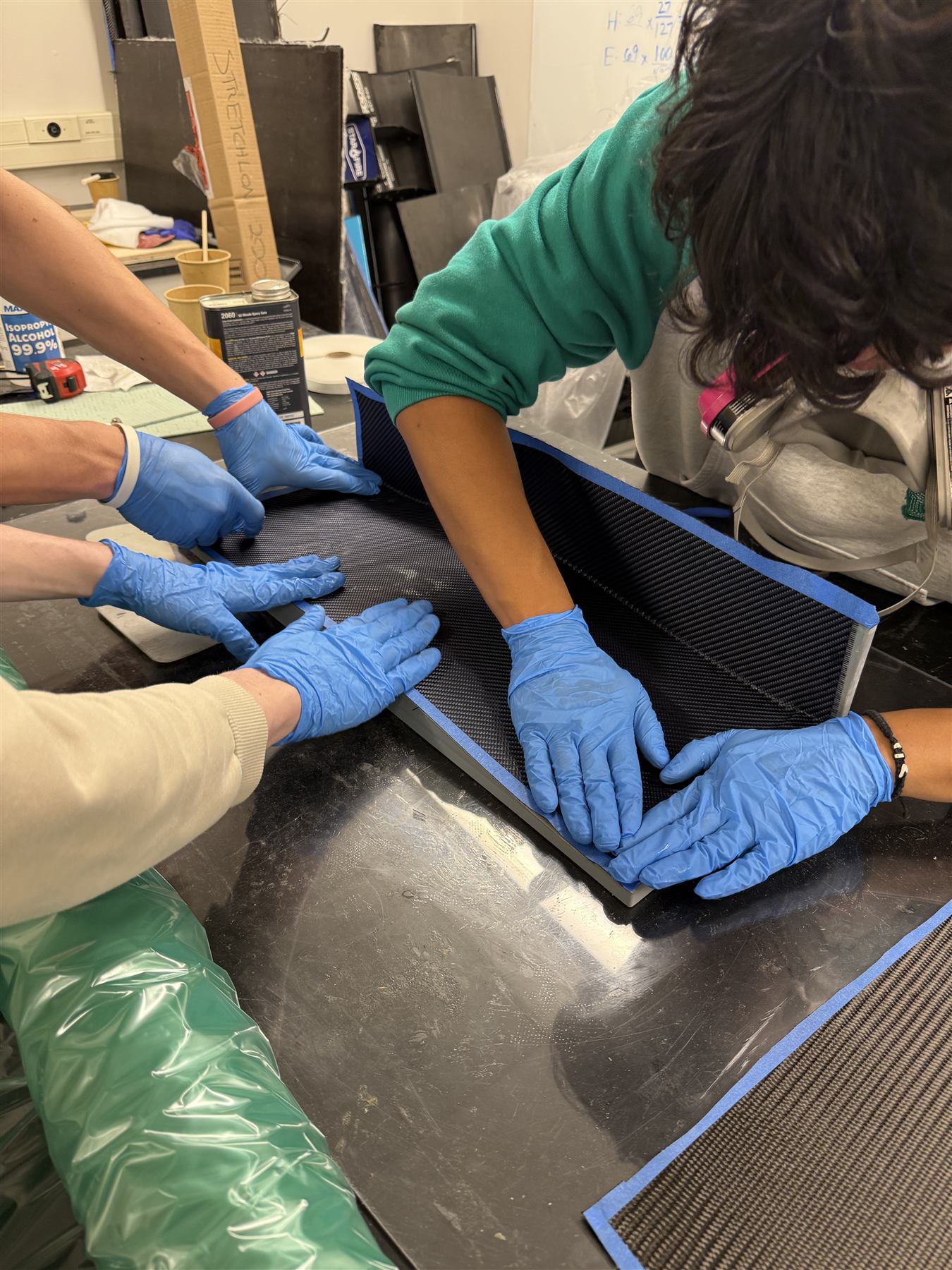
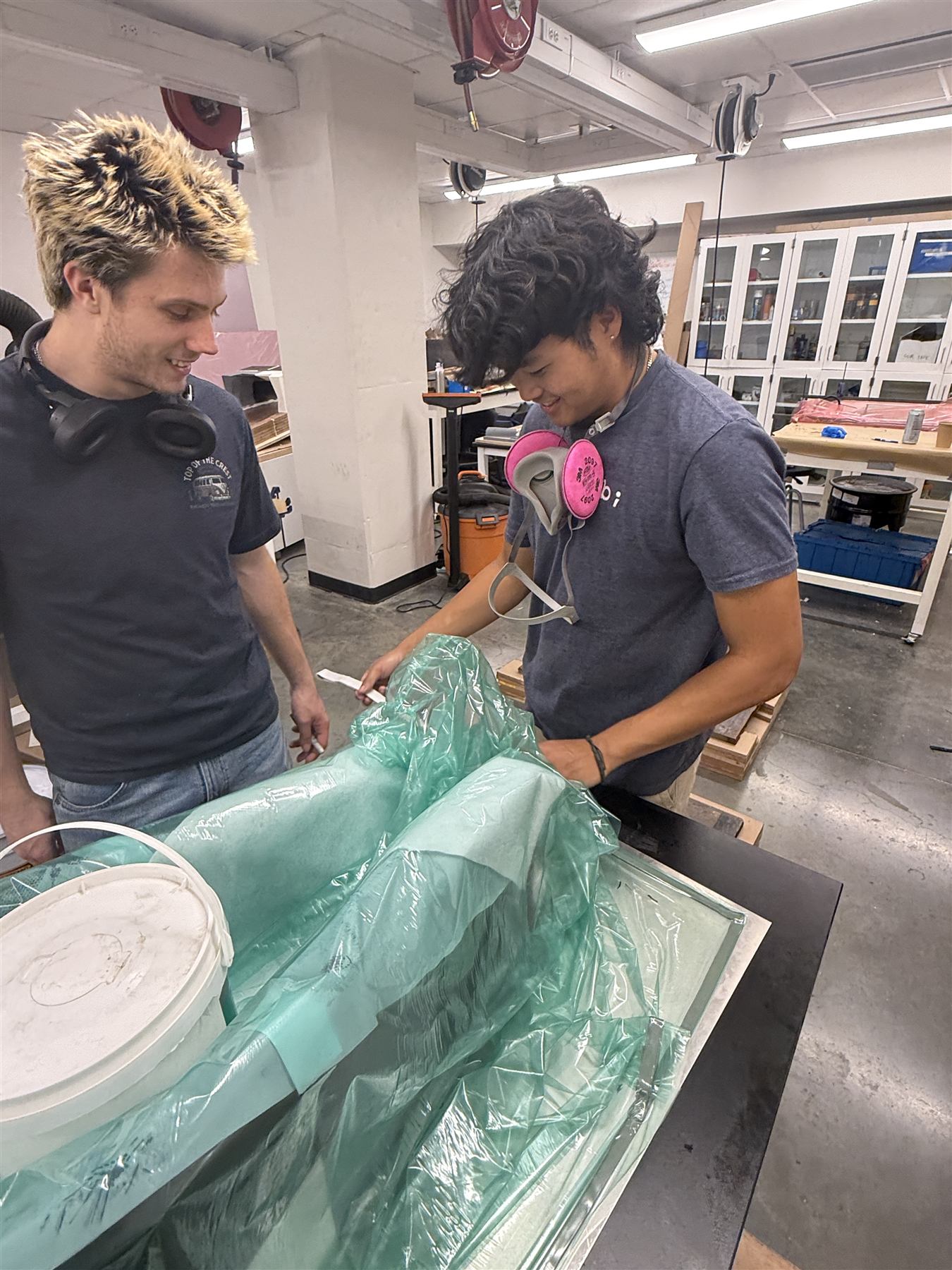
The process began with preparing molds made from 3D-printed PLA and CNC-routed MDF. Because every imperfection in a mold transfers directly onto the finished part, we gradually sanded surfaces through 1200 grit before applying release agents. Depending on the component, we used wet layup or vacuum-assisted resin infusion, along with peel ply, breather fabric, flow media, vacuum-bagging materials, and foam core, considering fiber placement, resin distribution, vacuum integrity, part thickness, structural stiffness, and whether the cured component could be removed from the mold without damage.

Once a part cured, it still required extensive trimming, fitting, and finishing. Edges had to be cut cleanly, mounting locations had to line up, and adjoining surfaces had to fit together without disturbing the intended geometry. Completed assemblies also had to maintain sufficient ground clearance, accessibility, stability, and mounting rigidity so they wouldn't shift or deflect under load.

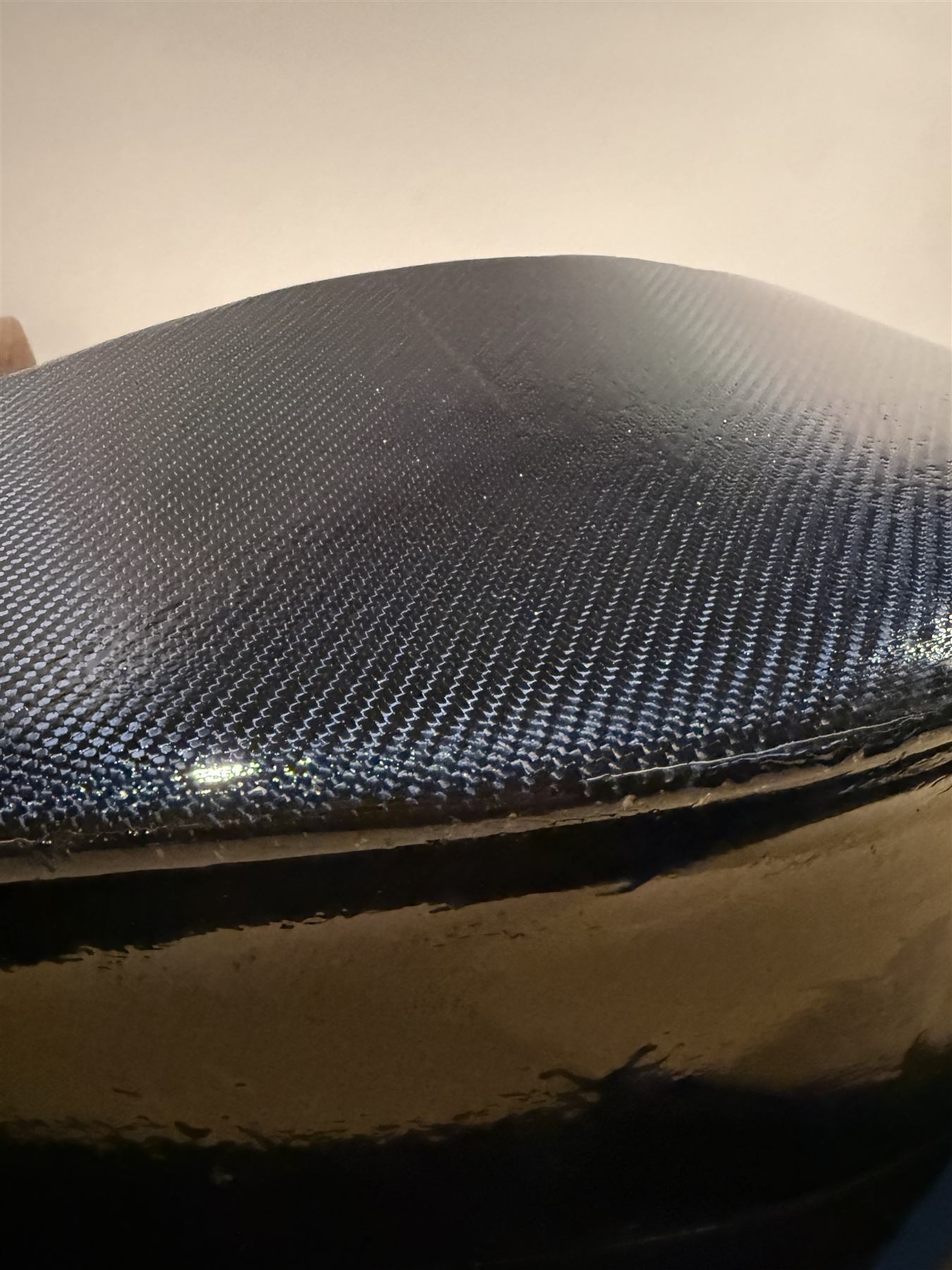
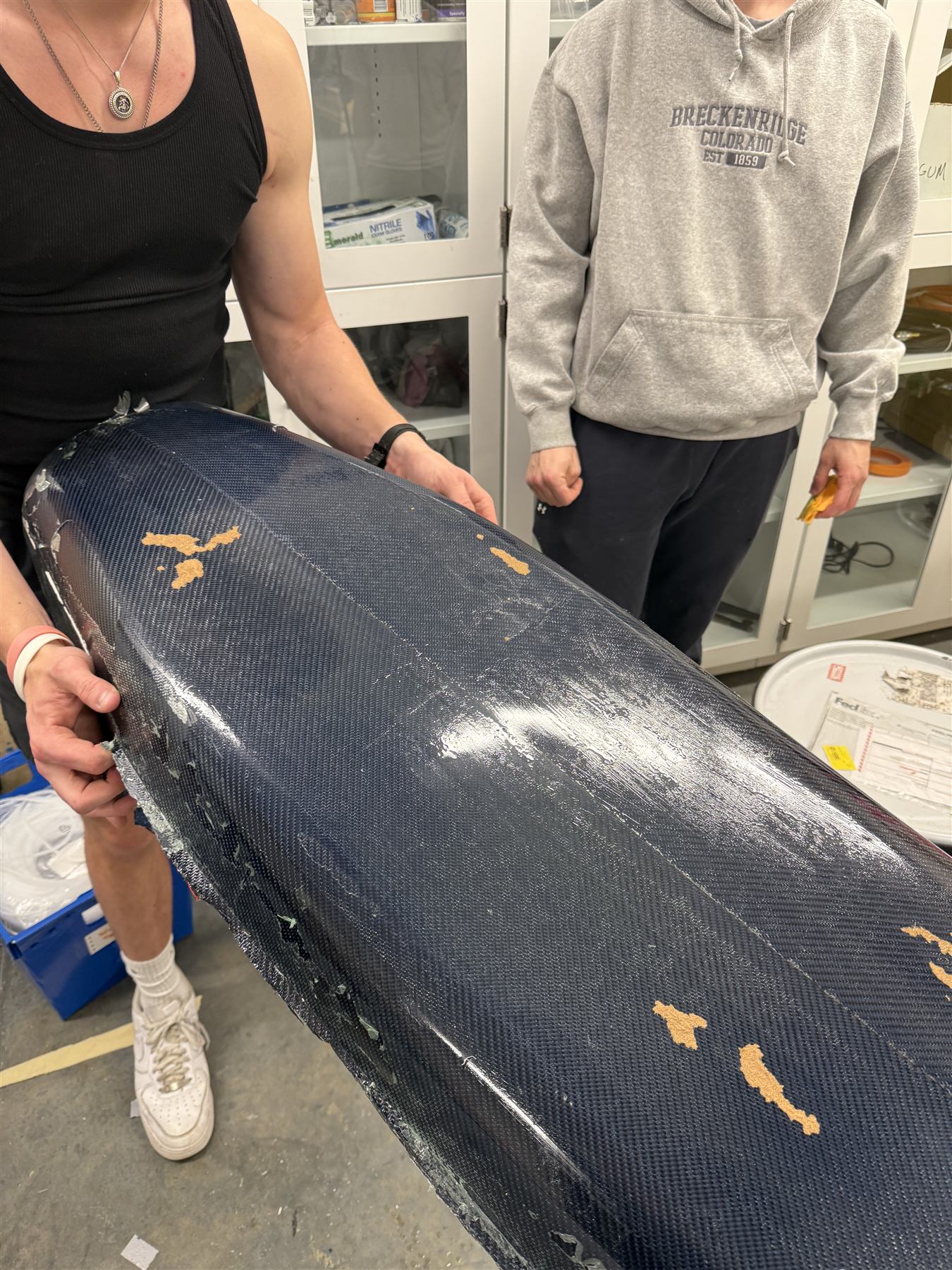
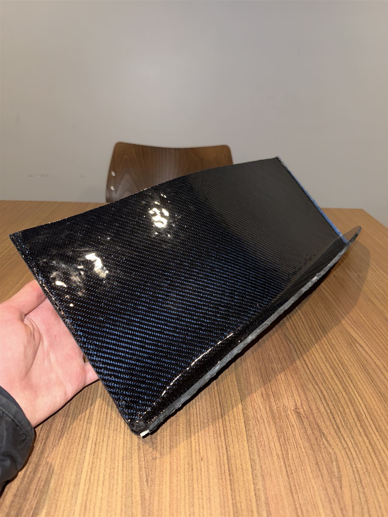
Surface finish was one of the most time-consuming parts of the process. Mold seams, print lines, pinholes, and uneven resin could leave the surface rough even when the shape was correct. We repeatedly sanded the parts, applied epoxy clear coats to fill and level the surface, then sanded and polished again for a smoother finish. This wasn't only for appearance. On an aerodynamic component, the exterior surface is the surface the air actually encounters, so waviness or exposed delaminated fiber takes away from the geometry meant to maximize aerodynamic efficiency. The goal was to preserve that geometry as closely as possible while giving the package a clean, competition-ready finish.
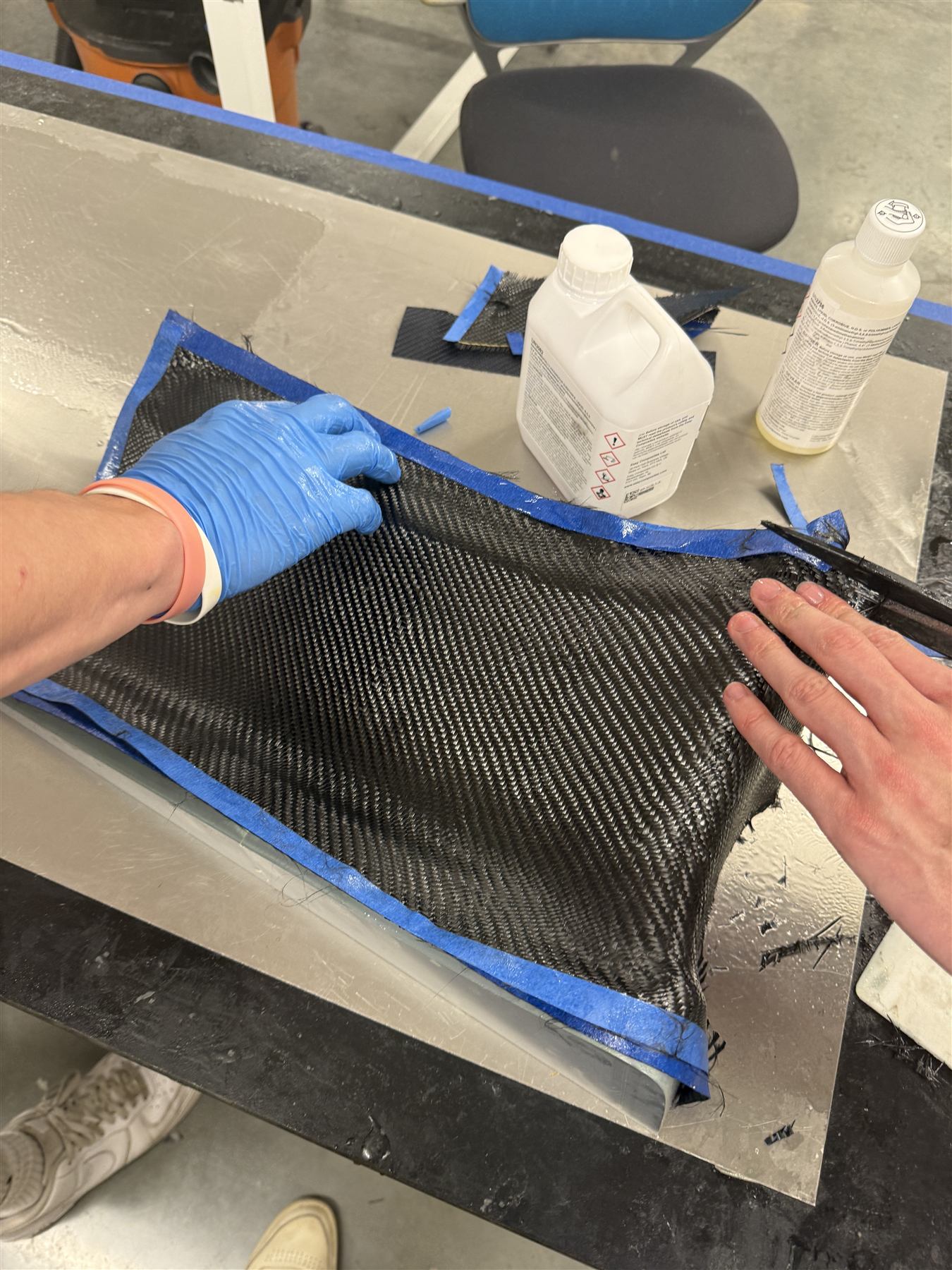
Finished 2x2 twill carbon-fiber weave, clear-coated
Wet layup of a carbon-fiber panel
Trimming a cured carbon-fiber panel edge
Vacuum-bag preparation for resin infusion
Undertray and diffuser vacuum-bagged for cure
Nosecone, fresh from the MDF mold
Nosecone, fresh from MDF mold
CNC-routed MDF mold, sanded and prepped
Final Assembly & Competition

As competition approached, the individual aerodynamic components finally became a complete package. The front and rear wings, undertray, nosecone, sidepods, and body panels had to be fitted and aligned around the finished car. This stage exposed issues that couldn't always be seen while working on each part separately. Mounting points, panel gaps, ground clearance, accessibility, rigidity, and the relationship between neighboring surfaces all had to be checked before VU17 could leave for Michigan International Speedway.

I was selected as one of only a few freshmen to travel with the team to Formula SAE Michigan IC 2026. The weekend gave me my first look at the intensity of an actual Formula SAE competition: technical inspection, design judging, last-minute repairs, and the constant pressure to keep the car running. Our first engine failed, forcing an overnight engine swap; the replacement then failed too. It was a difficult end to months of work, but that's part of racing.

During competition, I went into aerodynamic design judging with Connor Brett from the senior capstone team. Much of our discussion with the judges centered on simulation, physical validation, and whether our design decisions were supported by enough data from testing. We had some simulation results, but not enough to guide a complete cycle of testing and iteration, because the car had fallen behind schedule and most of our available time had gone toward manufacturing the package and improving its finish rather than validating how the full system performed together.

The experience made it clear that a well-manufactured part is not the same as a fully validated design. Our aerodynamic goals need to be defined more explicitly from the beginning, with measurable targets for downforce, drag, aerodynamic balance, and cooling, that then guide simulation, design changes, manufacturing, and physical testing instead of treating each stage as a separate effort.

Result

Our aerodynamic package received 8 out of 15 points in design judging: the second-highest score in our entire design bay, behind Georgia Tech (10). The result reflected the work behind a complete, well-finished package in only three months, and the judges' feedback gave us a clear direction for the next car.

This entire FSAE aerodynamics / composites manufacturing project was all made possible by the generous support and guidance of the senior capstone team as listed before, but also the company and assistance of Luke Gustafson '27, Matthew Parker '27, Luke VanEmburgh '27, and Randall Preson '29.

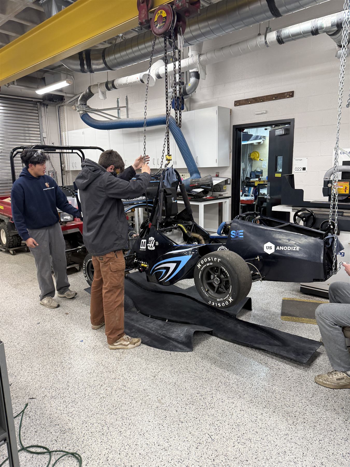
Mounting the undertray to the frame
Mounting the undertray to the frame with Jase and Chris, using metal zip ties and brackets I made on the manual mill
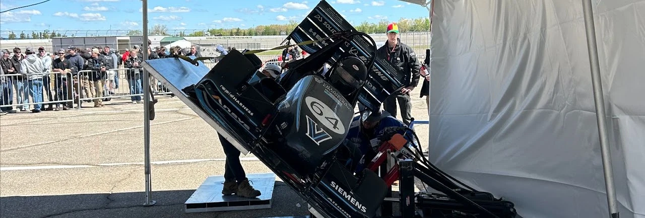
Tilt test, a static event that pushes the limits of the suspension assembly's structural integrity when fully loaded
Tilt test: a static event that pushes the limits of the suspension assembly's structural integrity when fully loaded
Some of the VU17 seniors in graduation gowns with the car outside a campus church
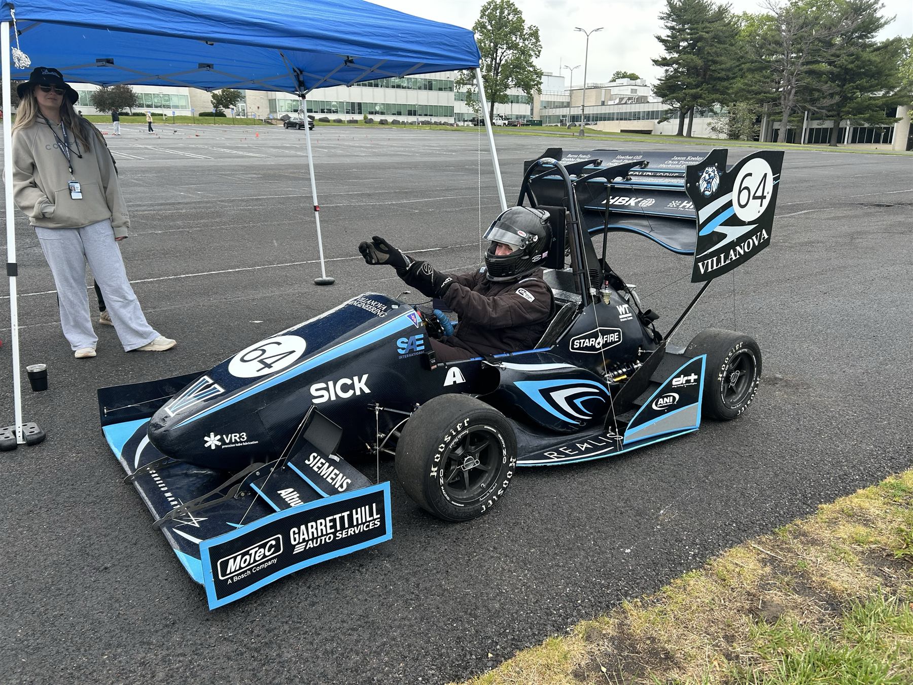
VU17 on track during a testing day after the build